

|  |  | The model |
The full model is defined as the composition of 3 components:
The command LUS2AUTOC then assemble these parts to generate a correct AUTOCs specification.
We just declare here some datatypes and synchronization channels used for the communication between the LUSTRE controller and its environment.
type stat = enum sidle,splus,sminus;
  -- used to model the disk motor device

channel cinput(real);
  -- Input of the Lustre controller (and output of the environment)
  -- Carries the speed of the disk
channel coutput(bool,bool,bool);
  -- Output of the Lustre controller (and input of the environement)
  -- Carries resp. plus, minus, and ok signal
node Controller(speed:real) returns (plus,minus: bool);
let
  plus = speed <= 8.0;
  minus = speed >= 12.0;
tel

node Property(speed: real) returns (ok: bool);
var cpt: int;
    acceptable: bool;
let
  acceptable = 8.0 <= speed and speed <= 12.0;
  cpt = 0 -> if acceptable then 0 else pre(cpt)+1;
  ok = true -> (pre cpt<=7);
tel

(* main node *)
node L(speed:real) returns
(
        ok: bool;
        plus,minus : bool;
)
let
  (plus,minus) = Controller(speed);
  ok = Property(speed);
tel
The disk controller works a follows. It receives the speed of the disk and emits appropriate signals plus and minus to maintain the motor speed within a specified range (here [8,12]). The controller include a property observer (node Property), which specifies the following property: whenever the speed has been outside the range for a given delay (here, 7), counted as a number of steps, a false ok signal is sent.
We want to verify that the ok signal is never sent. This means that, if the speed is initially 0, it must reach the correct range in time, and be properly controlled afterwards.
The command LUS2AUTOC will embed this Lustre program in a process as follows:

When inputs are received, they are used to compute instantaneously the outputs, but to model the reaction time, outputs are stored and later emitted on channel output.
The environment is the composition of the disk motor and sensor devices, the scheduler, and in addition the property observer.
The disk motor and sensor device is defined as follows:

process S {
sync cinput,coutput;
var s : real;
    stat : stat;
init pc=linit;

loc linit:
  continuous blocked;
  when speed=s and s=0
    sync cinput(speed)
    goto l assign { stat := sidle };
loc l:
  continuous
    (if stat=sidle then -EPS<=s and s<=EPS
     else if stat=splus then M-EPS<=s and s<=M+EPS
     else if stat=sminus then -N-EPS<=s and s<=-N+EPS
     else blocked);
  when true sync coutput(ok,pplus,pminus) goto l
    assign { stat := if pplus then splus
                     else if pminus then sminus
                     else sidle };
  when speed=s sync cinput(speed) goto l;
}
M, N, eps are parameters of the system (instanciated by the use of the M4 macroprocessor).
The device starts with a null speed. It can be in 3 modes: accelerating (stat=splus), decelerating (stat=sminus) and no action (stat=sidle). The derivative of the speed s lies between resp. [M-eps,M+eps], [-N-eps,-Neps] and [-eps,eps] in these modes. The process synchronize on channel cinput to semit the speed and on channel coutput to receive the plus or minus signals.
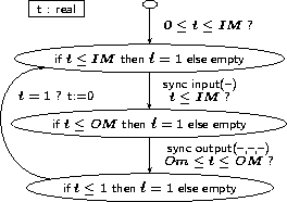
The scheduler defines the following scheduling for synchronization on channels cinput and coutput:


process X {
sync cinput,coutput;
var t : real;
init pc=linit;
loc linit:
  continuous blocked;
  when 0<=t and t<=DIM sync cinput(a) goto loutput;
loc linput:
  continuous if t<=DIM then t=1 else blocked;
  when t<=DIM sync cinput(a) goto loutput;
loc loutput:
  continuous if t<=DOM then t=1 else blocked;
  when t>=DOm and t<=DOM sync coutput(ok,a,b) goto lwait;
loc lwait:
  continuous if t<=1 then t=1 else blocked;
  when t>=1 goto linput assign { t:=0  };
}
DIM, DOm and DOM are parameters of the system (instanciated by the use of the M4 macroprocessor). Sampling of the inputs of the controller is performed in the interval [0,DIM], and outputs are emitted in the time interval [DOm,DOM]. The reaction time of the controller thus lies in the interval [DOm-DIM,DOM].
A full cycle is supposed to be 1 second here.
process E {
sync cinput,coutput;
init pc=linit;

loc linit:
  continuous blocked;
  when true sync cinput(a) goto l;
loc l:
  continuous anything;
  when true sync cinput(a) goto l;
  when true sync coutput(a,b,c) goto l;
}
This process actually does nearly nothing. It just memorizes whenever the first input has taken place.
We now specify how the whole system is built and which are the declarations to be passed to the verification tool.
system L,X,S,E;
  -- composition of 4 process
explicit X;
  -- keep explicit the control structure of X

-- to be passed to NBac:
#pragma control "L.output1,L.output2"
  -- conditions used for first partition refinement steps
#pragma final "E.pc=E.l and not L.output0"
  -- property: bad state defined as L.output0 (output OK in Lustre node 'L')
  -- is false, whenever the system has started (E.pl=E.l).

|  |  | The model |